You do not need an accout to report a problem with the wiki.
-
TechInfoDepot:JTAG/Discovering JTAG pinouts
This article was posted originally to the forum of the popular Kitz Broadband Information Site [1]. While the article isn’t directly related to the 2Wire or the TriMedia, it is re-posted here to assist others searching for JTAG pinouts on undocumented boards.
Most JTAG cables will work fine in the pinout discovery process, so long as there is a generic driver available for the cable.
Discovering JTAG pinouts on a PCB is a very common problem. For a given board, the size of the problem can be quantified using Probability Theory.
In the worst case scenario, using ‘brute force’ to discover the JTAG pinout means testing every possible permutation of JTAG signal and header pin.
Formally, the JTAG pinout problem is an r-Permutations challenge. It is described by the notation nPr.
nPr is the number of permutations, or ways to choose, an ordered subset of r items from a set of n objects.
In the case of the 2Wire boards, the set of n objects are a set of 14 header pins, or fingers of a card edge connector. From that set of n pins we need to discover the ordered subset of r pins carrying the JTAG signals.
The formula for nPr is n! / (n-r)! where ! is the factorial symbol, e.g. 7! means (7 x 6 x 5 x 4 x 3 x 2 x 1)
Out of the fourteen header pins on the 2Wire board, there are six candidate pins. Any of these six pins could potentially carry any of the five JTAG signals {TDO,TDI,TMS,TCK and TRST}.
Here, n is 6 (the number of candidate pins), and r is 5 (the number of JTAG signals).
So nPr = 6! / (6-5)! = 720 permutations.
However, some assumptions can be made which will radically reduce the search space.
One of the JTAG signals (TRST) is optional. TRST resets the JTAG controller when driven low. If we assume that, by default, TRST is pulled up to keep the board out of reset, it can be ignored.
Another JTAG signal (TDO) can be discovered from its floating logic state using an ohmmeter. This is very well explained by Ray “revspermin” Haverfield. [2] (one pin will have high resistance to gnd and 3.3v.)
That leaves us with just three JTAG signals to find from a choice of five header pins.
Now the scale of the problem is given by 5!/2 = 60 permutations.
That has already shrunk the search space by more than 90%.
We can now take advantage of another property of the JTAG standard. [3]
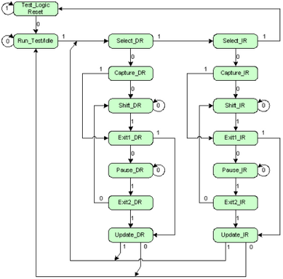
A JTAG controller will always return to its reset state when the TMS signal is asserted for five or more ticks of the TCK signal. This is illustrated in the attached diagram of the JTAG state machine.
The bit values {0,1} represent the transitional states of the TMS (Test Mode Select) signal. For example, to transition the JTAG state machine from the Shift_IR state to the Exit1_IR state requires TMS to be asserted for one tick of the TCK signal.
It doesn’t matter where you start in the state machine. When TMS is asserted and five ticks are clocked into TCK, it will always return the JTAG controller to its Test_Logic_Reset state:
Once a JTAG device is in its reset state, the 32-bit IDCODE is loaded into the JTAG data register. This loading is done automatically. It doesn’t require any instruction to be shifted in on the TDI line.
TDO was discovered earlier from its floating logic state. So what this means is that only the TMS and TCK signals need to be found at this stage. TDI can be found later.
By controlling just the TMS and TCK signals from software, the IDCODE value loaded on reset into the data register can be scanned out of the TDO pin. The TDO pin is closely monitored for output that is consistent with an IDCODE. [3]
Looking at this again as a combinatorial problem:
n remains at 5 since we still have five unknown pins. However, r, the number of signals to discover, is now just 2. These are the TMS and the TCK signals.
So nPr is 5!/3! = 20 permutations.
Using these techniques, the discovery of JTAG pinouts is trivialised.
There are software tools, such as JTAG_Finder [4] that can automate the fiddly task of swapping pins during pinout discovery. However, this is rarely necessary. Using the techniques above, the average count of pin-swaps before discovery is reduced to a manageable number.
In summary, and using the 2Wire boards as an example, a total of 14 pins were reduced to 6 candidate pins. TDO was discovered with an ohmmeter. TRST was ignored. The discovery of TDI was postponed. Software (UrJTAG) was used to navigate the JTAG state machine for each permutation of TCK and TMS, chosen from the five remaining pins. Using these shortcuts, the average count of pin-swaps needed to discover TMS and TCK is reduced to just 10.
With just three pins left, discovery of TDI will take 1½ further pin-swaps on average. In the example above, discovery of all the JTAG signals should take an average of 11½ pin swaps.
External links
[1] http://www.kitz.co.uk/
[2] http://forums.whirlpool.net.au/forum-replies.cfm?t=808533&p=9&#r176
[3] http://www.xilinx.com/support/answers/11857.htm
[4] http://elinux.org/JTAG_Finder
